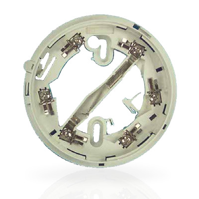
The Tyco 4B 4" Universal Detector Base (part number 517.050.041) is a common fire detection system component designed to provide a secure and reliable mounting platform for compatible Tyco fire detectors.2 It's classified as a "Universal" base, meaning it's used in installations where a short circuit isolator or continuity functionality is not required.
Features
- Continuity, Isolator and Universal variants
- Quick and easy to install
- Compatible with 800, 814, and 850 Series detectors
- Park position for testing
- Optional detector locking device
- Slim 4-inch profile
- Snap-fit to Ceiling Tile Adaptor
- Optional detector locking device.
- Break-outs for surface mount wiring.
4-Inch Base Options
The 4B-C Continuity base is used for most
installations involving 850 Series detectors, as it
allows the detector’s in-built short circuit isolation
function to be in-circuit when the detector is
fitted and ensures continuity is maintained
when the detector is removed. The 4B-I Short
Circuit Isolator base is used to protect circuits
that use devices that do not have built-in shortcircuit isolation. The 4B Universal base is used
when neither short circuit isolator nor continuity
functionality is required. All 4-inch bases are
compatible with the Ceiling Tile Adaptor that can
potentially decrease installation time by up to 30%.
Fixing
The 4B detector bases are designed to snap-fit to the
Ceiling Tile Adaptor. Alternatively they can be screw
fixed to a ceiling, electrical box, or deckhead mount
in the traditional manner. A park position allows the detector to be mechanically attached to the base
without making electrical connection to facilitate the
testing of electronic-free bases.
The base should be fixed such that the park plunger
faces toward the door or trafficable area. This ensures the detector LED will be visible from the direction of
entry, in accordance with AS1670.1-2004.
With a detector mounted in the base, a raised rib on
both the base and detector align when the detector is
in the fully home position.
Wiring
Cables should be arranged at each side of the terminal screw. A maximum of two 1.5mm2 cables or one 2.5mm2
cable can be fitted to one terminal. Any additional cables (such as Remote Indicator) should be fitted with suitable
fork or eyelet crimp terminal lugs. The installation should comply with AS 1670.1 or NZS 4512.
L (-In/Out) L1 (+In/Out).
A remote indicator may be
connected between loop positive
L1 (+In/Out) and terminal R (-ve).
Terminal L2 must not be used.
Detector Lock
The detector locking device is part of the base moulding. If required, it is detached and
inserted into the locking aperture. A detector mounted in the base will now be locked in
position. The detector can then be removed only after inserting an unlocking tool into the
hole on the detector cover to depress the spring tab on the locking device. A 3mm rod
could be a suitable unlocking tool; one can be fabricated by grinding a screwdriver with a
3mm diameter shaft to a length of 22mm.The detector locking device is part of the base moulding. If required, it is detached and
inserted into the locking aperture. A detector mounted in the base will now be locked in
position. The detector can then be removed only after inserting an unlocking tool into the
hole on the detector cover to depress the spring tab on the locking device. A 3mm rod
could be a suitable unlocking tool; one can be fabricated by grinding a screwdriver with a
3mm diameter shaft to a length of 22mm.
LED Aperture Plug
Bases with an isolating function have an LED fitted. Bases without an isolator have an empty aperture, which may
be filled using a plug detached from the base moulding.Bases with an isolating function have an LED fitted. Bases without an isolator have an empty aperture, which may
be filled using a plug detached from the base moulding.
Maintenance And Service
The Tyco MX addressable system should be maintained in accordance with the relevant parts of AS 1851 or
NZS 4512. The Tyco X300 Smoke Tester, X461 Heat Tester and CO test gas (part no. 517.001.262) may be used for
testing the detector in-situ. Rotating the detector anticlockwise past an indent to the park position disconnects
the detector from the circuit whilst still retaining it in the base, allowing loop testing etc. Depressing the plunger
at the side of the base allows the detector to be rotated back into its operating position.
